Building from first principles
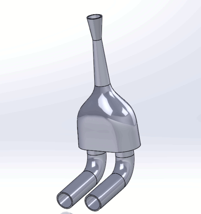
At its core, an intake manifold is just the engine's air pump. Its only job is to get as much air into the cylinders as possible, as efficiently as possible, because more air means more fuel can be burned, and more fuel burned means more power. Everything about designing one comes back to that single goal: move air with as little resistance and as much tuned velocity as you can manage.
- Restrictor: This is the bottleneck the rules force on you. The goal isn't just to follow it, it's to minimize its effects.
- Plenum: This is the volume that has to have enough air for the cylinders. Make the volume too small and the pressure pulses of the intake starve the cylinders, make it too large and the throttle performance becomes sluggish because too much air has to move before the engine feels a difference.
- Runners: Length is everything here. Air moving down a runner behaves like a wave, and if you tune the length so that reflected pressure waves arrive back at the valve right as it's closing, you get a free power boost from resonance.
Restrictor Design
The FSAE rulebook for 100-octane-fueled vehicles dictates that they must have a 20mm diameter restrictor located after the throttle body. The way the restrictor works is quite simple: once the restrictor hits choked flow, the mass flow rate through the restrictor becomes capped. At engine speeds past this point, the amount of air into the engine is now capped, reducing your top end power.
To solve this, I focused on reducing the pressure drop through the restrictor. Less pressure drop means the air flowing through the restrictor retains more of its original pressure and density, meaning that the pistons have to work less hard to pull air into the cylinder. Denser air allows the engine to pack more oxygen molecules into the same cylinder volume, allowing the engine to inject more mass per intake stroke.
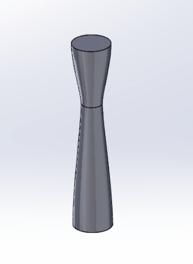
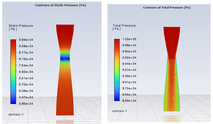
After making a CAD model of the restrictor, I used ANSYS Fluent to run sweeps over many different converging and diverging angles, simulating the restrictor at choked flow. I then picked the top 3 restrictors with the lowest pressure drop to move forward with in my design.
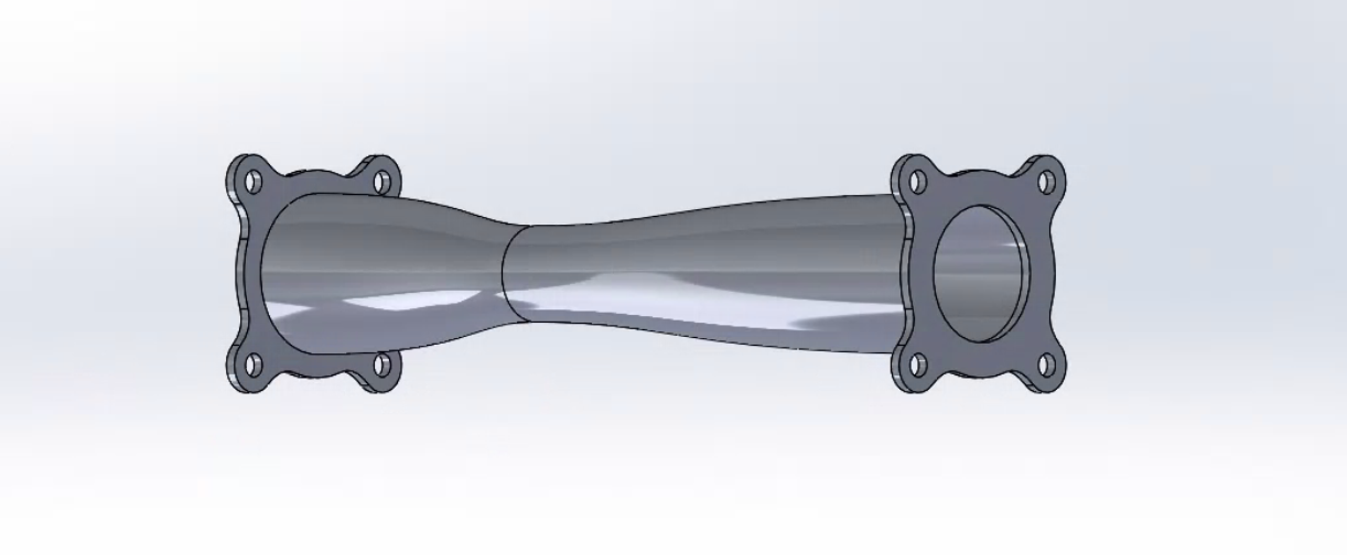
Picking the best one
Ideally, I would just pick the restrictor with the lowest pressure drop and call it a day, but unfortunately it's never that easy. The placement of my intake manifold restricted the maximum height of my restrictor, so I had to pick the restrictor that was the shortest and also had the least pressure drop.
Plenum Design
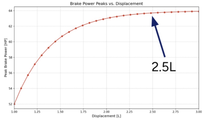
Optimizing the size of the plenum is not as easy as optimizing the restrictor, as there's not just one dominant figure in play. The plenum needs to be correctly sized and also shaped in a way to reduce vortices while delivering an equal amount of air to each cylinder. To optimize size, I utilized a GT Power model and did sweeps over many different plenum volumes. After doing this, the software gave me 2.5L as the ideal plenum volume. To optimize the shape, I once again turned to ANSYS Fluent and did many design cycles to end up with a design that had no vortices and equal air in each cylinder.
Runner Design
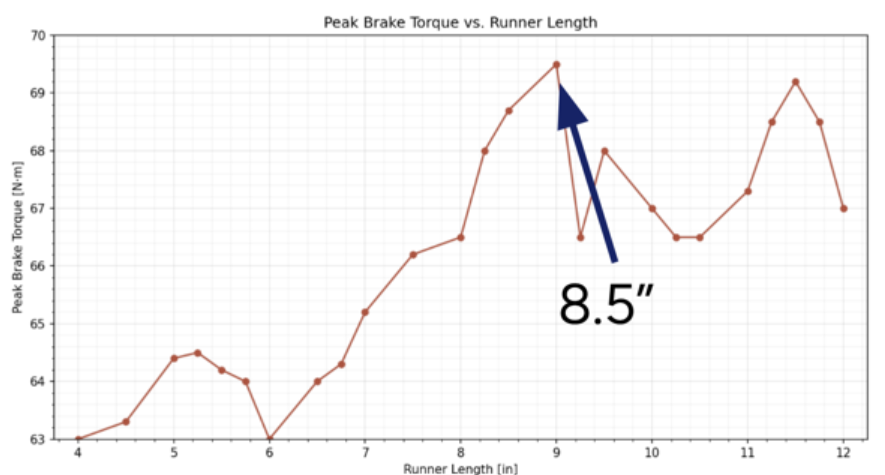
Runner design, if you deep dive into it, is the most complicated of the three. In a simplified example, when an engine's intake valve closes, the high-pressure air in the runner suddenly hits a wall. This causes a pressure wave to bounce back through the runner. When it reaches the plenum, some of that energy is lost to the plenum volume, but some is reflected back. Optimizing the runner length means you'll get more power at a given RPM, which in my case I wanted to line up with my engine's peak power RPM. I swept runner length in GT Power and landed on 8.5", which lined up peak torque right where I wanted it.
Structural Design
An intake manifold functions as a pressure vessel while also being rigidly attached to an engine, which vibrates across a wide range of frequencies, and that engine is in turn mounted to a car, which has its own vibrational modes as well. To make things worse, with the air filter being at the top of the vehicle, the intake is also acting as a cantilever beam.
With the organic shape of the intake manifold, I decided to utilize additive manufacturing to make it. At first, I decided to use FDM printing with CF-Nylon filament. I attempted to run vibration simulations across my engine frequency range, but since I was not able to include the vibrational mode of the actual vehicle and the model was very simplified, I wanted to go with the strongest material available and test it on the vehicle.
One of the first issues with FDM 3D printing an intake manifold is sealing it to prevent air leaks. To do this, I applied a single thin layer of epoxy to the outside of the intake to seal any air gaps at the layer lines. The epoxy held up fine, but after testing the manifold on the vehicle, it ended up breaking at a layer line due to the excessive deflection from vibration at the top of the manifold.
To fix this, I added a support for the intake manifold at the top of the vehicle, while also switching to SLS printing for the manifold. This both reduced the vibrational load of the intake manifold and removed the stress concentrations of the layer lines.