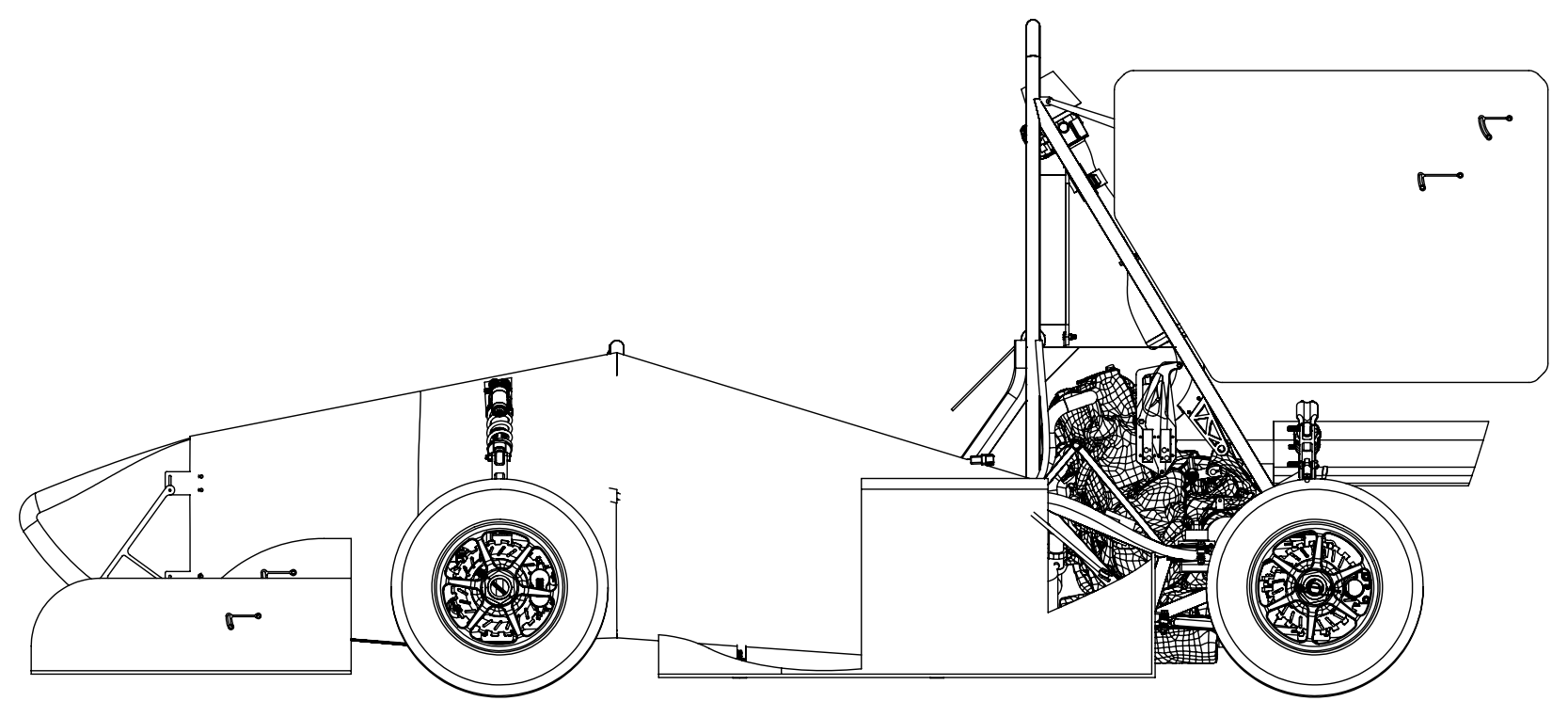
Overview
For the Duke Motorsports 2025 and 2026 FSAE cars, I served as one of the Powertrain Leads. My role on the team was to lead the overall design of the engine-side powertrain system, specifically:
- GT Power Modeling: refined the team's engine simulation model to more closely match real chassis dyno data.
- Intake Manifold: designed the restrictor and intake manifold, full write-up here.
- Exhaust: redesigned the exhaust for long tube headers
- Fuel System: optimized fuel injectors, fuel pump, and fuel tank sizing
- Shifting: redesigned our shifting system to pneumatic to make our shifts quicker.
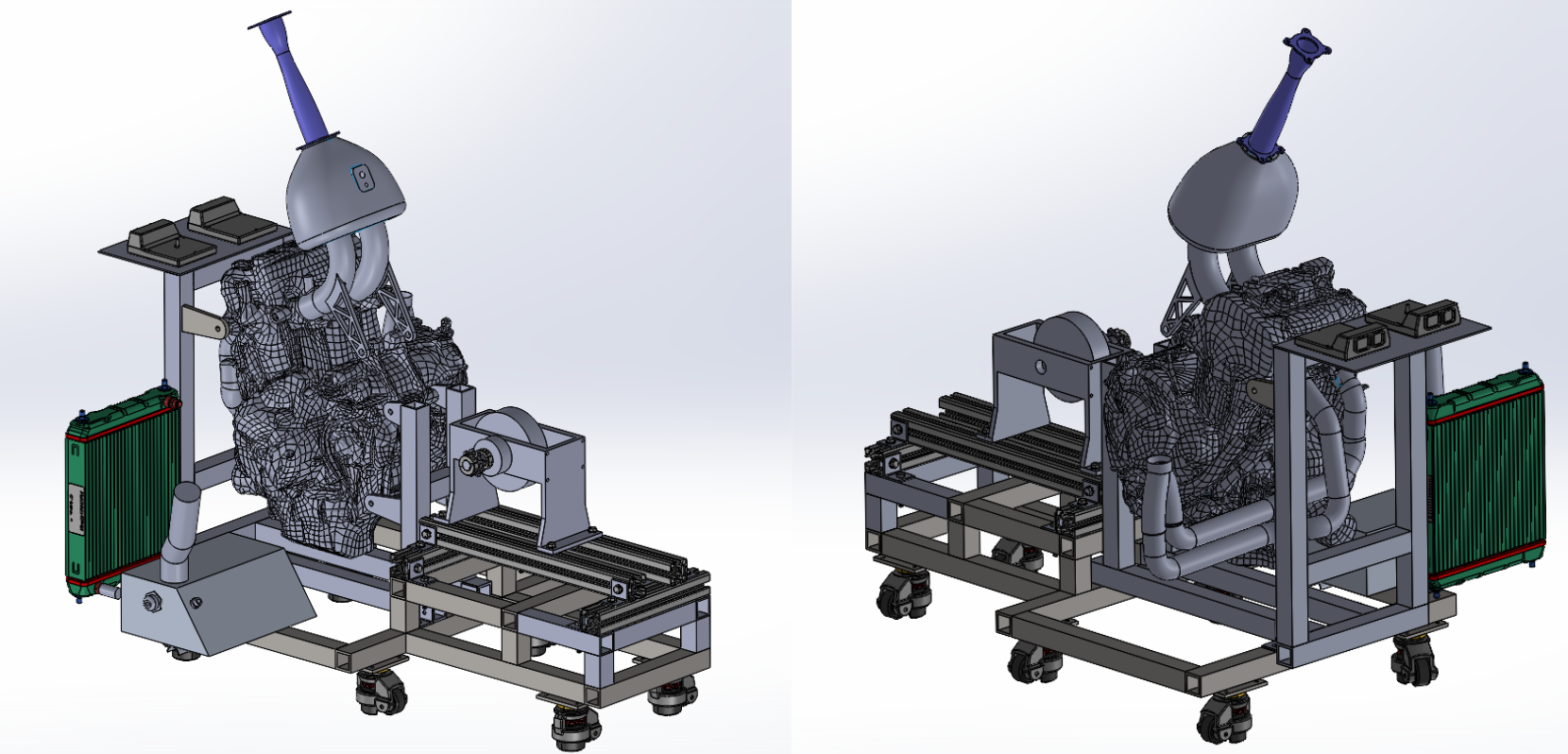
- Dyno Development: designed engine dyno stand for future use
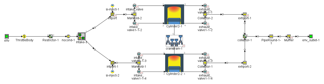
GT Power Model
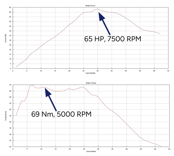
The first goal of mine sounds simple, make more power. However, how do you figure out where the most power is left to be gained? At this stage, I did not have access to an engine dyno where I could test many different designs. I only had access to a single day of chassis dyno data.
We already had an existing GT Power model that was developed in years prior, but after comparing the models output with the chassis dyno data they were vastly different. My work was spent refining this model, specifically remeasuring the intake and exhaust valve timing as well as recreating the models for the intake manifold and exhaust system to be more accurate with our vehicle. This resulted in our GT Power model much more closely following the chassis dyno results with the only deviation being at low RPM.
Shifting
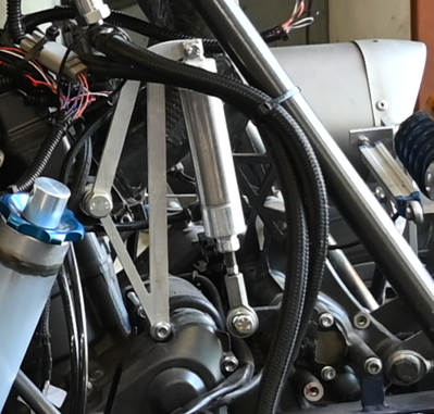
This was one of the largest changes I made for the 2026 vehicle's powertrain system. In previous years we would run a servo system, which would shift slow and not allow our drivers to properly downshift in corners. Due to this, I decided to switch the system to a pneumatic one, using a piston to shift the engine.
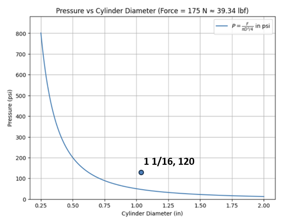
There are two main things to optimize in a pneumatic shifting system, your piston and air tank. For piston sizing, I found the amount of force required to shift the engine using a force gauge and used that to spec out a piston size using the graph below.
For the air tank, I used the ideal gas law to figure out how much air mass gets used per shift, then scaled that up to size the tank:
M = p1V / RT1 = (101365 N/m² · 1.45×10⁻⁵ m³) / (287 J/(kg·K) · 300 K) = 1.71×10⁻⁵ kg, or 0.017 grams per shift
That works out to needing about 17.5 grams of air for 1025 shifts, which is roughly how many shifts I expected across a competition weekend. From there I sized a 35ci tank that could hold enough pressurized air to cover that without needing a refill.
Since this calculation treats the system as an ideal gas at a constant temperature and pressure, I applied a large FOS on top of the tank size instead of sizing right to the calculated minimum. In reality this isn't an ideal system. Rapidly releasing compressed air through the solenoid and piston is closer to an adiabatic process than an isothermal one, so the air actually cools and loses some density as it expands, which means less mass makes it to the piston per shift than the math assumes. There's also pressure loss through the lines, fittings, and solenoid valve that the calculation doesn't account for at all, along with some amount of leakage in the system over time. All of that eats into the usable air, so I'd rather have leftover capacity in the tank than run out of shift air partway through an endurance run.
Dyno Development
Something big our team lacked, which heavily impaired our ability to do a real-world, data-driven powertrain design, was an engine dyno. Previous students on our team laid the groundwork to start an engine dyno by purchasing the equipment necessary but we were missing the actual stand that allowed us to connect our engine to our dyno. The dyno that they chose was a small engine waterbrake dyno, which at first seemed to line up with the torque band of our engine. However, since motorcycle engines have the transmission included, the output torque values ended up being out of range for the dyno. To solve this, I designed a stand that geared up the output of the engine to bring the torque back within the range of the waterbrake dyno using two sprockets and a chain.
One big potential issue is with this is that the power figures that the engine dyno reads may not be accurate, as there are some losses within this additional sprocket and chain. However, since the engine dynos purpose is to simply compare the real world differences between broader powertrain design, as long as the system is the same between tests it does not matter.
Engine
The engine we run is a 689cc 2 cylinder Yamaha CP2 engine. It provides great low end torque and high end power while being in a 2 cylinder package, making it easier to design and package the rest of the powertrain system.
This year, I wanted to fully understand the engine stock before I dove into changing the internals of the engine. Therefore, I focused heavily on understanding the tuning of the engine.
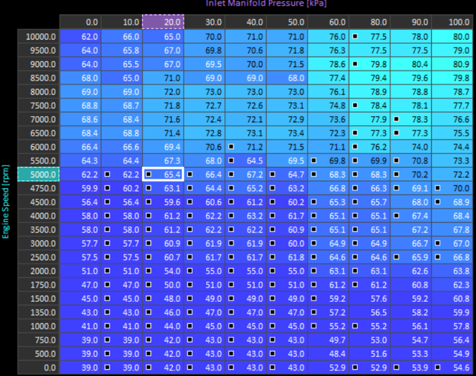
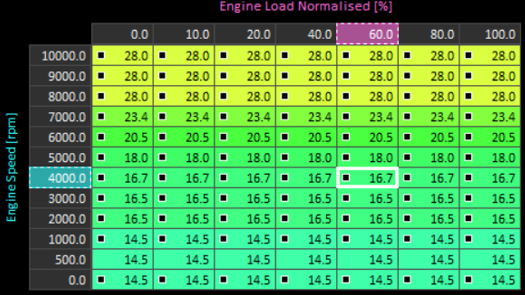
I only had one day of chassis dyno time, so I used it to dig into our VE and fuel maps directly instead of just logging pulls. VE, or volumetric efficiency, is basically how well the engine fills its cylinders with air compared to its theoretical max at a given RPM and load, and the ECU leans on a VE table to figure out how much air is actually in the cylinder so it can pull the right amount of fuel from the fuel map. That one day was enough to clean up our steady state fueling, but not enough to dial in how the engine behaved during transients, throttle tip-in, gear changes, stuff like that. So after the dyno day, I did a lot of the transient tuning out on the road, logging runs and adjusting the maps based on how the car actually felt and responded.
Exhaust
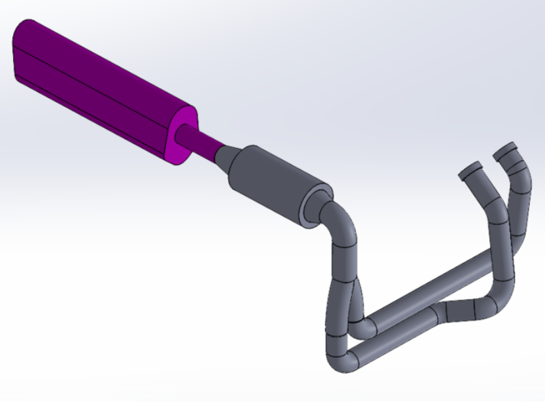
In previous years, due to packaging constraints, we ran unoptimized short headers. Optimizing our exhaust header length is just as important as optimizing our intake runner length for a similar reason: the pressure waves. When the exhaust valve closes, a low pressure wave follows the pulse of exhaust gas. If the length is optimized, this low pressure wave arrives back at the exhaust valve and helps pull more exhaust air out, allowing cleaner air to fill the cylinder.
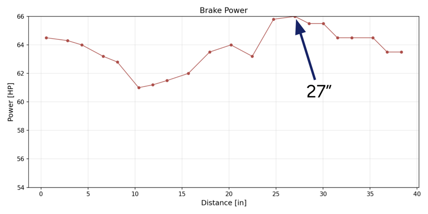
To optimize for exhaust header length, I once again turned to my GT Power model and ran sweeps over many header lengths, picking the one that saw the most power increase at the RPM band I wanted while still being able to be packaged in the vehicle.
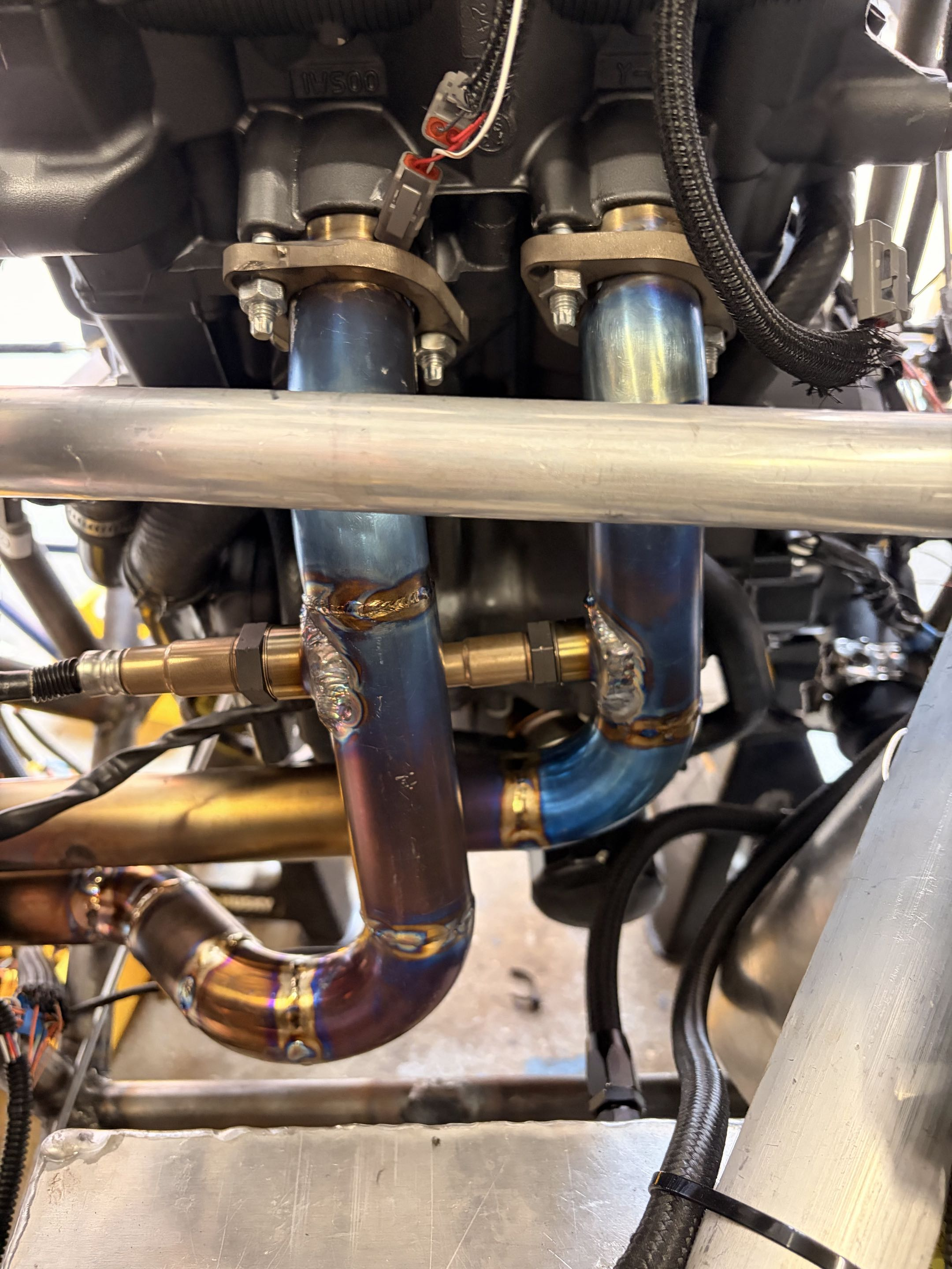
Lastly came material selection, since we acquired a titanium sponsor, we ended up making our exhaust out of titanium. Titanium's superior heat retention allows our exhaust gas to stay hot, allowing it to flow better through the system. It also allowed us to take no weight penalty compared to our stainless steel short tube headers even with the increase in total tubing.
Fuel System
Our fuel system was made up of 4 parts: the fuel rail, fuel injectors, fuel regulator, and fuel pump.
First, starting with the fuel rail. This design was mainly dictated by our injector o-ring sizing and distance between the engine intake ports. For our fuel regulator, I picked one that was readily available and light. For the fuel pump, the external fuel pump options that are readily available are all designed for much larger engines so there was not much to be gained optimizing here.
That leaves two things, the fuel tank and the fuel injectors. Here is where the most optimization of the fuel system can come from. A properly sized fuel tank can both make your overall car lighter and also make packaging your powertrain system much easier. To size the fuel tank, I used our previous car data to find our fuel consumption rate, and then applied that rate for the full endurance course. To be safe, I applied a 1.5X FOS.
For the fuel injectors, the goal was to find the smallest injector that could still supply enough fuel at peak power without going over a safe duty cycle. Flow rate scales directly with horsepower and BSFC, and inversely with the number of injectors and the duty cycle you're targeting:
Flow Rate = (HP · BSFC) / (# Injectors · Duty Cycle)
I didn't have real fuel flow data to calculate BSFC, so I pulled it straight from my GT Power model instead: 0.2092 kg/kWh. That's not the same as measuring it, and it comes with some error since the model was only validated against a single day of chassis dyno data, and even then it didn't perfectly match at low RPM. If the model's fuel consumption prediction is off, my flow rate calculation is off by the same amount. To account for that, I picked an injector that cleared the calculated flow rate with margin instead of matching it exactly.
Plugging in my 58.84 HP target, a conservative 80% max duty cycle, and my 2-injector setup gave a required flow rate of 16.96 lbs/hr. I picked the smallest commercially available injector that cleared that number.
I didn't just round up to whatever injector had the most headroom though. Bigger injectors flow more fuel per pulse, so at idle and low load, where the engine barely needs any fuel, the injector has to open for a really short pulse width to avoid running rich. Injectors aren't very linear or repeatable down near their minimum pulse width, so an oversized injector makes idle and part throttle tuning a lot harder to dial in, even if it has plenty of headroom at peak power. Picking the smallest injector that cleared my required flow rate kept me inside its usable pulse width range across the whole RPM band, not just at redline.